Mar 22, 2017
Discussion:
This lesson continues our quest of learning more about programming and electronics. In previous lessons, we already discussed several reasons why we have chosen to use an Arduino board as the tool to help us learn.
Specifically, we chose the Arduino Uno board. The Uno is the baseline Arduino board, being the one around which other Arduino boards are designed .
Therefore, the Uno is a great place for us to start digging in. It’s also a fantastic launchpad if you decide to move on to other platforms in the future.
In this lesson, we'll do a high-level overview of the Arduino Uno hardware. Specifically, we’ll cover:
- The Concept of an Arduino Board
- The Three Types of Pin Header Rows: Digital, Analog, and Power
- Other Miscellaneous Valuable Tidbits
The Concept of an Arduino Board
As we discuss the hardware, I recommend holding your Arduino board in your hand. Pause the video as needed to take a closer look at the board as we discuss the different components.
First, I want to point out that the integrated circuit is the brains behind the Arduino board. It’s very likely that the circuit is the Atmel ATmega 328, which is an 8-bit microcontroller.
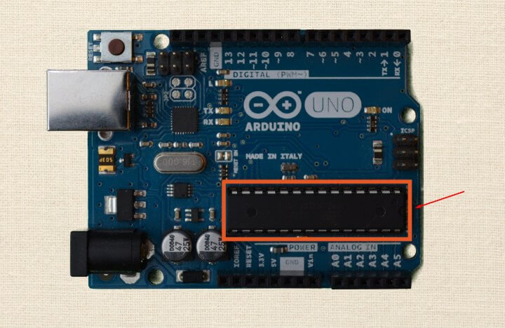
Don't worry about that fancy name. The only thing I want you to understand is that everything on the Arduino board is meant to support that integrated circuit. So, the Arduino exists to make it easy to use this microcontroller.
If you look closely at the microcontroller, it may look slightly different from mine, depending on which model you have. It might be really small, called a surface mount component, or it could be a big one like mine, which is called a DIP.
Either way, there will be little metal prongs that stick out of the side. These are called pins.
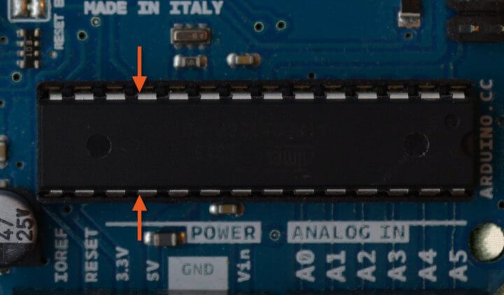
These pins are how the microcontroller is able to do stuff. These are used to interface with other hardware and circuitry, such as LEDs, sensors, or even your computer.
Therefore, we need to know how to actually connect them to other things. That's where the pin headers come into play.
Pin headers, sometimes referred to as just headers, are the plastic rows of holes that stick up from the Arduino board. They are all along the border.
Inside of the holes are little metal clips. When you stick a wire down into the hole, that wire will stick and stay there.
For example, you can stick the wire that comes out of an LED or a resistor into those holes. The wires are called leads, by the way. The wire makes an electrical contact in that hole.
In other words, the wire sticks in the pin header. The metal clamp inside the header clamps onto the wire, and an electrical connection between that wire and a specific pin on the microcontroller is then created.
Digital Pin Headers
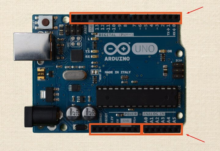
There are three categories of headers: digital, power, and analog. The first one we’ll discuss is the digital category.
Digital pin headers make up the longest row on the Arduino board.
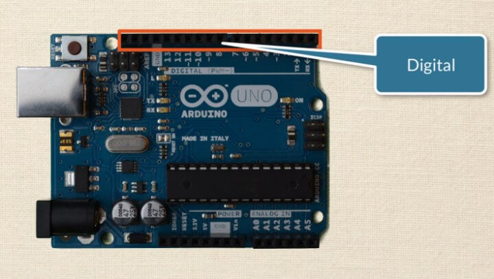
They are numbered from zero to 13. That means there are a total of 14 digital pins that we can use.
To make this lesson as practical and easy as possible, for our purposes when I say digital, I mean something that is a discrete state.
Let's use color as an analogy. Something that is digital can only be either black or white. Digital does not care about any point of gray in-between.
Therefore, digital pins are used in one of two ways. They can be used as inputs to do things like read a voltage. Otherwise, they are used as outputs, such as applying a voltage.
When they operate as an input, they can only read two different voltage states - high or low. The same is true when they act as outputs. They can only output two voltage states - five volts (high) or zero volts (low).
Just as in anything else in life, there is an exception to this. You'll notice that some of these pins have a little squiggly mark next to them.
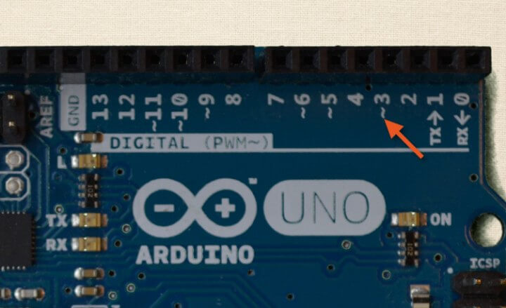
There should be six of them, located at pins three, five, six, nine, 10, and 11. These specific pins allow you to use a technique called pulse width modulation, or PWM.
PWM is a technique that we'll dive into later in the course. It enables us to use digital pins in such a way that they appear as though they are outputting a varying amount of voltage.
Again, we'll get into PWM in much greater depth later. Right now I just want to point out those pins, and why they are special.
I also want to point out two other pins. Notice that pins zero and one have a “TX” and “RX” next to them with little arrows. That stands for transmit and receive.
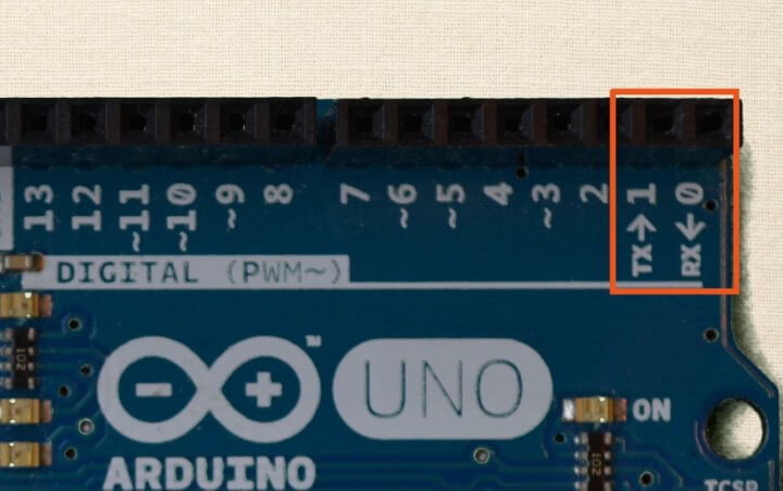
The Arduino uses these two pins to communicate between the board and the computer. For example, maybe you need to upload your code.
Maybe executing your sketch performs serial communication between the Arduino and the computer. Serial communication is another concept we'll be learning later in the course.
It’s only important that you understand these pins used to transmit and receive. Therefore, it’s best to only use pins zero and one as a last resort if you’ve run out of available pins.
The reason for this is that sometimes adding additional circuitry to these pins can interfere with serial communication. This will make a lot more sense when we get to that section of the course. For now, just know it’s a good rule of thumb to leave pins one and zero alone.
There are also two on-board LEDs labeled “TX” and “RX”. These blink every time you send information back and forth between the Arduino Uno and the computer.
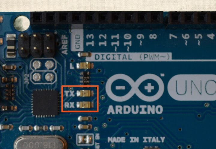
If you have the Arduino hooked up, and it’s supposed to be communicating with the computer, you should see these blinking. If not, it’s a good indication that you probably don't have the Arduino set up correctly in the IDE, and communication is unsuccessful.
Lastly, pin 13 is also worth noting.
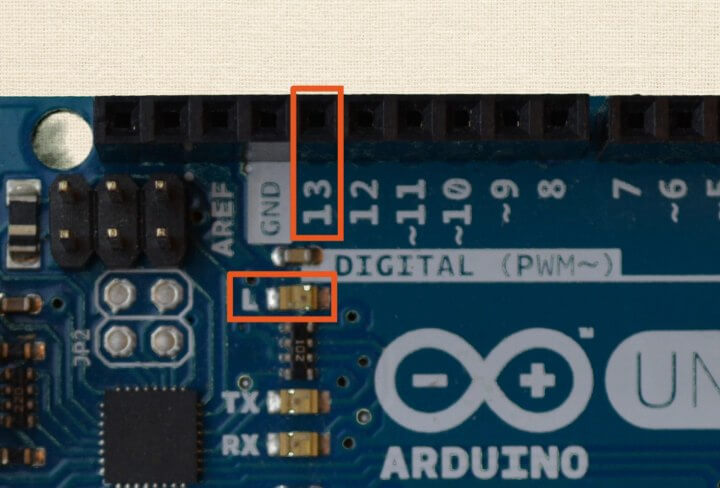
That is where an on-board LED is attached. You can use that LED as though it were externally connected through a resistor to the Arduino.
Analog Pin Headers
The next category of headers are analog pin headers. These are labeled A0 through A5, giving us six analog pins.
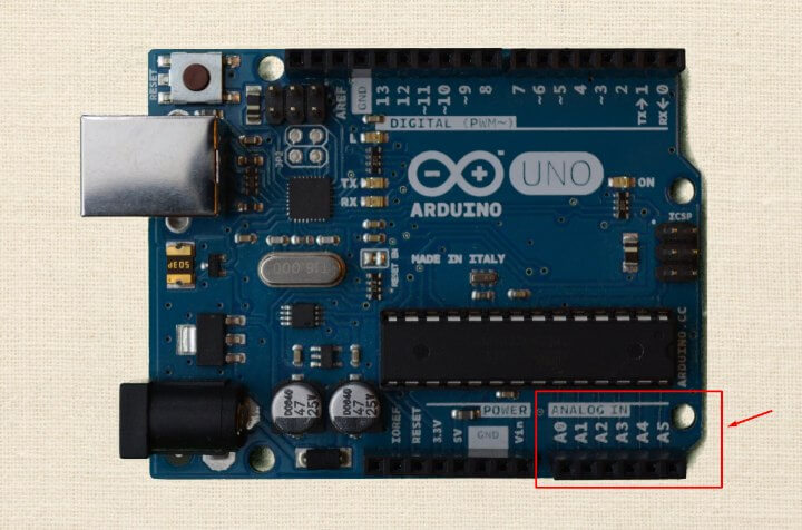
As you might have guessed, “A” stands for analog.
Before we said that digital means discrete states - either high or low, one or zero, black or white. However, analog is a lot more colorful.
When we say something is analog, it means that it can be in any number of states. Analog embraces all of the various shades of gray between black and white.
Many sensors create analog signals. They're not just on or off. They can be all of the states in-between.
However, our integrated circuit really only knows discrete digital states. Therefore, the microcontroller handles analog inputs by using a tool called an analog-to-digital converter, or simply an ADC.
The ADC is part of the integrated circuit, built right into the chip. The analog pins have access to it.
The ADC takes all of the variation in an analog signal and cuts it up into discrete steps. In other words, instead of having an endless list of possibilities from your low to high limit, the ADC would cut that expanse from the low value to the high into a certain number of “chunks”.
In addition to being able to use the ADC, analog pins can also act just like digital inputs or outputs. So, they are very versatile. We’ll do a deeper dive on this later in the course, as well.
Power Headers
The last row of pin headers is the power header row. They are next to the analog headers.
There are only a handful of pins I want to point out right now. The first one is labeled “5V”.
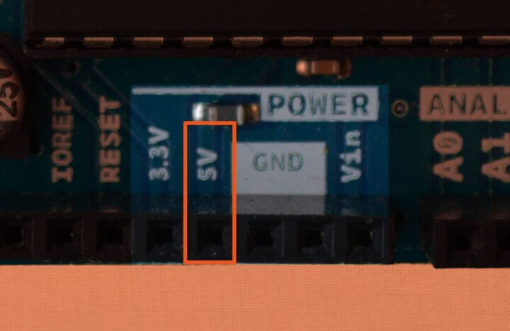
That stands for five volts. If you have the Arduino hooked up to the computer via USB, or if you have external battery power applied, this pin can provide five volts to a circuit. We'll be using this pin extensively throughout the course when we're setting up our circuits.
The pin next to it is labeled “3.3V”, which stands for 3.3 volts.
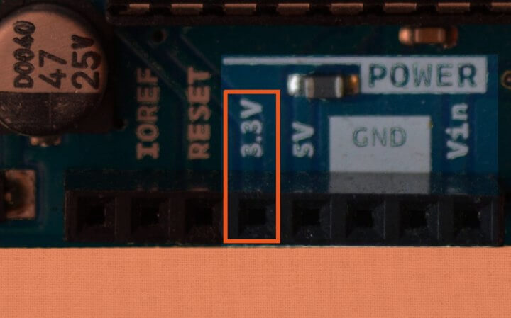
Obviously, it provides 3.3 volts to the circuit.
Next to these pins are two pins labeled “GND”, which stands for ground.
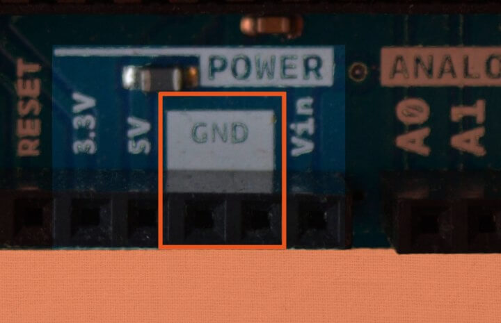
These two pins give us access to the lowest voltage on the Arduino board, which is zero volts.
Miscellaneous Goodies to Know
There is yet another ground pin located up next to the digital header row.
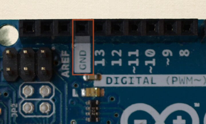
It’s important to keep in mind that all of these ground pins are one in the same. They are all connected to each other. Therefore, throughout the course when we set up our circuits, it doesn't matter which one you decide to use.
Let me make one final note about the pin headers. You may hear a term thrown around called the “Arduino Footprint”. That’s simply how the Arduino headers are aligned.
If something is said to match the "Arduino Footprint", it means that it has that same header layout as the Arduino board. The most common example of this would be an Arduino shield because, by default, the headers on a shield are almost always going to match the board.
That term is not really all that important to know, but I wanted to make sure you had heard the term if you ran into it.
Another item that is helpful is the reset button.
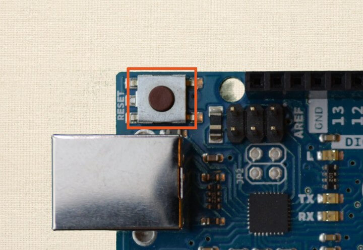
Just as the name implies, when you press that button, the program currently running on your Arduino board will start back at the beginning. It doesn't erase the program. It just starts the program over.
There is also a reset pin on the Arduino.
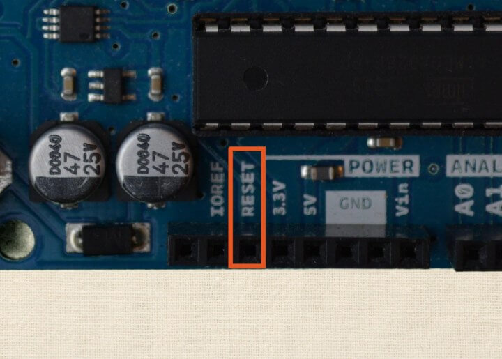
If you apply a low voltage to that pin, it does the same thing as the reset button. It will reset the current program running on the Arduino.
Next, the Arduino Uno has a power on LED.
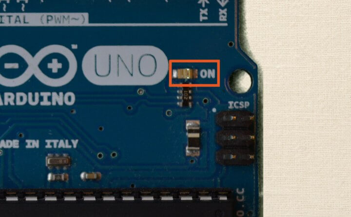
It is illuminated anytime power is being applied to the Arduino. This is true no matter if the Arduino is powered through a USB cable or through an external power jack.
Review
Wow! Lots of components! How about we go back over the highlights?
We talked about kind of the overall concept of the Arduino board. It is built to support the integrated circuit.
We also discussed the three different pin header rows. We went into detail about the digital, analog, and power headers.
Finally, we covered a few miscellaneous components. The Arduino Uno has a reset button, a reset pin, and a power on LED.
Hey, don’t worry if you still have a lot of questions! That's to be expected this early in the course. A lot of terminology and some new concepts were thrown around.
Remember, though, this was only meant to be an overview of the Arduino hardware. As we move further into the course and delve deeper into the specifics of these concepts, it will all begin to come together. Patience, young grasshopper.